Why Choose the Right Hydraulic Coupler for Your Equipment?
A hydraulic coupler may look like a small connection, but it has a demanding job. It transfers pressurized fluid between equipment components while helping limit leaks and contamination. The wrong choice can restrict flow, create excess heat, or make routine attachment changes difficult. Small parts matter.
Choosing a Hydraulic Coupler starts with the equipment’s specifications, not appearance alone. Check the required pressure and flow rate, connection type, size, and operating temperature. A coupler rated for the machine’s pressure may still cause problems if its internal passage is too narrow. That detail is easy to overlook. Dust, grit, and trapped air can also affect performance, especially when connections are made outdoors or during frequent tool changes.
Material and seal compatibility deserve equal attention. A coupler exposed to weather, vibration, or corrosive fluids may need different materials than one used in a clean workshop. Confirm compatibility with the hydraulic fluid and follow the equipment manufacturer’s guidance. Then consider practical details: how easily the parts connect, whether they are accessible with gloves, and how they can be inspected for wear. In real use, even a technically suitable coupler can frustrate operators if it is awkward to reach. No single design suits every machine. The right choice balances system requirements, working conditions, and maintenance needs, with room to reassess when operating conditions change.
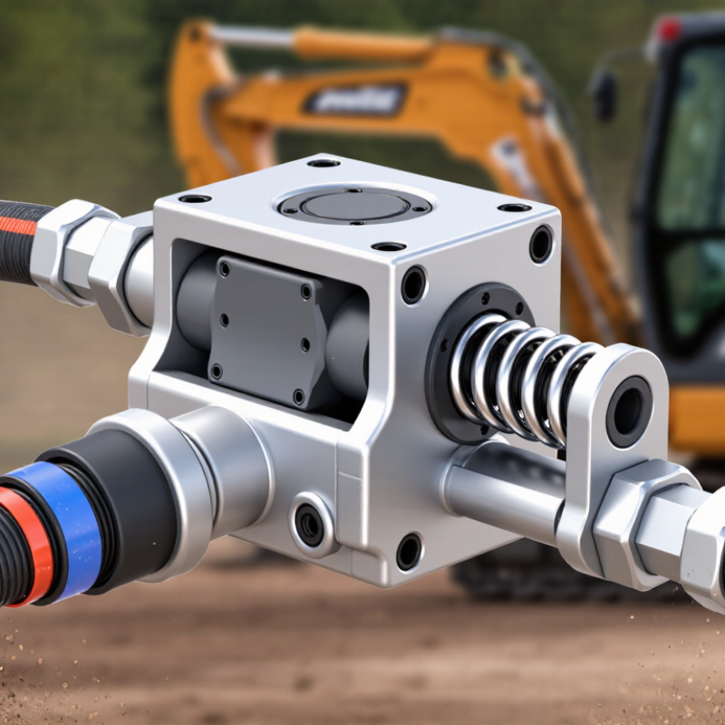
Identify Coupler Types: ISO 7241 Series A/B and ISO 16028 Flat-Face
The right hydraulic coupler depends on the connection standard, not just hose size. ISO 7241 covers Series A and Series B quick-action couplings, with distinct dimensions and connection details. Match the complete profile to its mating half. Appearance alone can mislead. ISO 16028 specifies flat-face couplings, designed to reduce fluid loss during disconnection and make exposed faces easier to wipe. Cleaner, not mess-free.
Before choosing, check working pressure, flow rate, temperature, and the machine’s connection standard. A mismatch can restrict flow or prevent a secure connection. ISO 4406:2021 classifies hydraulic-fluid cleanliness using particle counts across three size ranges: 4, 6, and 14 micrometres. That matters because grit on a coupling face can enter the circuit when connected. Keep caps on during storage, and inspect sealing surfaces for scratches. One awkward detail: a familiar thread or color-coded cap does not prove compatibility. Confirm the specification in the equipment manual and verify the exact ISO series; field assumptions sometimes get it wrong.
References: ISO 7241-1/-2; ISO 16028; ISO 4406:2021.
Record Equipment Pressure (bar) and Flow Rate (L/min) Before Sizing
Before choosing a hydraulic coupler, record the equipment’s working pressure in bar and flow rate in L/min. Use a suitable gauge and flow meter, and take readings while the machine performs its normal task. A pressure reading taken with the system idle may not show what happens under load. Record the operating condition beside each measurement, such as lifting a bucket or running an attachment. Numbers tell a story.
Note both steady pressure and any brief spikes, if your instruments can capture them. Check the equipment manual for rated limits, and never exceed them to obtain a reading. Measure flow at the attachment circuit when possible; pump capacity alone may not reflect flow reaching the coupler. Do not guess. Repeat readings if results vary, and write down the range rather than keeping only the highest number. A notebook entry may look untidy, or one reading may be off. That is a reason to recheck, not to hide the uncertainty. With pressure and flow documented, compare coupler specifications against the actual operating range, including hose size and connection requirements. A mismatch can cause heat, pressure loss, or restricted performance.
Why Choose the Right Hydraulic Coupler for Your Equipment? - Record Equipment Pressure (bar) and Flow Rate (L/min) Before Sizing
Record operating pressure and flow under the conditions in which the equipment will be used. Flow is a key factor in selecting a coupler size; confirm that the chosen coupler’s pressure rating, flow capacity, fluid compatibility, and connection type meet the equipment requirements.
| Equipment / Circuit | Operating Pressure (bar) | Measured Flow (L/min) | Provisional Nominal Coupler Size | Sizing Check |
| Compact loader auxiliary circuit | 180 | 25 | 3/8 in (DN 10) | Check rated working pressure and pressure drop at the measured flow. |
| Agricultural implement hydraulic line | 160 | 45 | 1/2 in (DN 12) | Verify flow capacity and compatibility with the implement’s connection. |
| Excavator attachment circuit | 250 | 75 | 3/4 in (DN 19) | Confirm coupler and hose ratings exceed the circuit’s maximum working pressure. |
| Industrial hydraulic power unit | 210 | 120 | 1 in (DN 25) | Check the manufacturer’s flow-versus-pressure-drop data for the exact coupler. |
| Low-flow control or pilot circuit | 70 | 8 | 1/4 in (DN 6) | Confirm the coupler is suitable for the circuit pressure and fluid. |
Important: Nominal sizes shown are preliminary examples, not universal flow or pressure ratings. Actual capacity varies by coupler design, connection standard, fluid, temperature, and allowable pressure drop. Always verify specifications for the exact coupler and equipment before installation; depressurize the system before connecting or disconnecting.
Match Coupler Flow Capacity to the Machine’s Δp–Flow Curve
A hydraulic coupler’s flow rating means little without its pressure-drop conditions. Compare its Δp–flow curve with the machine’s operating curve at the expected oil temperature and working load. If a machine needs 60 L/min, a coupler marked for 60 L/min may still impose excessive pressure loss at that flow. Check the actual curve. A few extra bar can slow an attachment and turn useful hydraulic power into heat. In practice, measure flow under load; a cold workshop test can be misleading.
The U.S. Department of Energy’s 2006 report, Improving Pumping System Performance: A Sourcebook for Industry, estimates that pumping systems use nearly 20% of global electricity demand. That figure covers pumping broadly, not couplers specifically, but it shows why system losses deserve attention.
For hydraulic oil, estimated heat loss is Δp × flow: with pressure drop in bar and flow in L/min, kW ≈ bar × L/min ÷ 600.
Compare candidate couplers at the machine’s real operating point, then confirm pressure and temperature during a loaded test. The neatest curve match on paper may not survive worn fittings, warm oil, or a slightly different duty cycle.
Check Series-Specific Interchangeability and Connection Compatibility
Hydraulic couplers can look almost identical and still fail to connect safely. The key is confirming the series, not just matching nominal size. ISO 7241:2017 specifies dimensional and performance requirements for quick-action couplings, with separate requirements for Series A and Series B. A matching diameter alone does not prove interchangeability.
Check the equipment manual and the coupler markings, then compare plug and socket profiles, locking grooves, seal arrangement, and connection threads. Thread type and pitch matter: a fitting may start to turn but still fail to seal. Also verify the working-pressure and flow ratings against the machine’s specifications. A restricted passage can cause heat and pressure loss. A quick visual check can miss that.
Tips: Measure thread pitch with a gauge, and compare the coupler profile against the relevant ISO 7241 series dimensions. Test the connection at low pressure before returning equipment to service. Even careful checks can overlook wear on an older socket; replace questionable parts rather than forcing a fit.
Verify Working-Pressure Ratings and System Safety Against ISO 4413
Why Choose the Right Hydraulic Coupler for Your Equipment?
Verify Working-Pressure Ratings and System Safety Against ISO 4413
A coupler’s pressure rating must match the system’s real operating conditions, not just the pump’s nameplate. Check maximum working pressure, pressure spikes, temperature, and the ratings of both coupling halves. ISO 4413:2010 sets general safety requirements for hydraulic systems, including attention to pressure limits, leakage, and stored energy. A pressure gauge can mislead. It may not capture a brief spike when a valve shifts or a heavy load stops suddenly. Confirm the equipment manufacturer’s specifications, then select a coupler rated for the actual duty. Never assume two parts are compatible because they connect.
The stakes are practical. The U.S. Bureau of Labor Statistics reported 5,283 fatal work injuries in 2023, with a rate of 3.5 per 100,000 full-time-equivalent workers. This figure covers all industries, not hydraulic incidents specifically, but it underscores why equipment hazards deserve careful controls.
Before maintenance, isolate the energy source and release trapped pressure using the approved procedure. Inspect seals and connection faces for cuts, wear, or contamination; a small leak can become a high-pressure hazard. Record the coupler’s pressure rating and inspection date. Check again after a repair or system change. Honestly, paperwork alone is not protection; the operator still needs clear procedures and training.