
What Are the Top Aluminum Extrusion Die Types in 2026?
Choosing the right Aluminum Extrusion Die can shape a project’s cost, strength, and production efficiency. In 2026, manufacturers will continue to rely on several established die designs, each suited to different profile geometries and production needs. A simple solid die can form a flat bar or angle, while hollow profiles often require more complex tooling. The details matter.
This guide examines the leading die types, including solid, hollow, and semi-hollow designs, along with porthole and bridge configurations. It explains how each design handles metal flow, profile shape, and manufacturing demands. For example, a hollow window frame may need a die that joins metal streams inside the tool, while a solid channel can use a more direct opening. Even small changes in wall thickness can affect the design.
There is no universal best die. Selection depends on alloy, press capacity, profile dimensions, tolerances, and expected production volume. Tooling teams also consider bearing lengths, thermal behavior, and how easily a die can be maintained. These factors are not always obvious from a profile drawing alone. Some choices still involve trade-offs, and practical trials may reveal issues that calculations miss. The sections ahead compare the main options and outline what to assess before committing to a design.
How Aluminum Extrusion Dies Shape Profiles
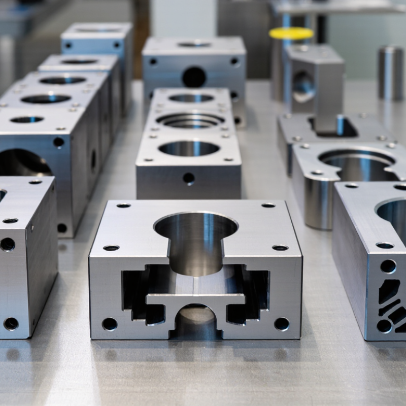
Aluminum Extrusion Dies turn heated billets into profiles by forcing metal through a shaped opening. The die’s geometry determines the profile’s outline, wall thickness, and dimensional limits. A solid die suits simple shapes, such as flat bars. Hollow profiles, like window frames, usually need a porthole or bridge die. These split the metal flow around supports, then reunite it inside a welding chamber. The seam is easy to overlook.
Small design choices matter. Thin walls and sharp corners can restrict metal flow, raise pressure, or cause uneven cooling. Die designers use bearing lengths to balance flow across the opening. A longer bearing slows metal in a fast-flowing area; a shorter one lets slower areas catch up. It takes careful adjustment. Billet temperature, alloy, press speed, and die wear also affect the finished shape, so a profile that works on paper may need revisions on the press.
Demand adds pressure to get these details right. The International Aluminium Institute has projected that global aluminum demand could rise by nearly 40% by 2030 compared with 2020. That forecast spans many uses, not extrusion alone, but it underscores the value of efficient material use.
A well-matched die can reduce scrap and help maintain consistent dimensions. Still, there is no universal “best” die: profile complexity, production volume, and tolerances all shape the choice.
Solid Dies for Simple, Uniform Cross-Sections
Solid dies are used to produce aluminum profiles with a continuous, solid cross-section. Think of flat bars, angles, channels, and trim with no enclosed hollow spaces. The billet is heated, then pressed through a shaped opening in the die. Simple geometry does not mean effortless production. The metal still needs to flow evenly across the opening.
Die designers adjust details such as bearing length, the section that guides metal as it exits. A wide area may need a different bearing length than a thin edge. This helps reduce uneven flow, twisting, and inconsistent dimensions. Press speed, billet temperature, and die condition also affect the result. Small changes can show up as a bowed bar or a rough surface.
Keep the profile practical. Very thin walls and sharp corners can be harder to produce consistently, even in a solid shape. Check the intended dimensions against the extrusion press and alloy before finalizing the die. A trial run can reveal issues that drawings miss. It is tempting to treat a simple cross-section as a simple die job. That assumption can be wrong.
Hollow Dies for Enclosed and Multi-Channel Profiles
What Are the Top Aluminum Extrusion Die Types in 2026?
Hollow Dies for Enclosed and Multi-Channel Profiles
Hollow dies create profiles with enclosed spaces, such as tubes, window frames, and multi-channel sections. A mandrel forms the inner openings while the surrounding die shapes the outer surface. In many designs, metal flows through separate channels and rejoins in a welding chamber under pressure. The resulting seam is usually part of the profile’s structure, not a visible defect. Still, uneven flow can leave weak spots or inconsistent wall thickness.
Die design depends on profile geometry, alloy, press capacity, and required tolerances. A narrow channel may cool differently from a broad one, so the metal can exit at uneven speeds. That can cause twisting or dimensional drift. Careful flow balancing helps, but it is not a magic fix; billet temperature and press conditions matter too. Complex profiles often need trial runs and adjustments before production settles down.
Tips: Check wall thickness around each hollow section, not only the outside dimensions. Ask for seam locations and inspection criteria before approving a die. Small design changes can improve metal flow, though they may also alter the profile’s function. At times, the simplest cross-section is still difficult to extrude consistently.
| Die type | How it forms the hollow section | Typical profile applications | Key advantages | Main design considerations |
|---|---|---|---|---|
| Porthole (bridge) die | Bridges support a mandrel while the billet is divided into metal streams. The streams pass through separate ports, weld under heat and pressure in the die’s welding chamber, then flow through the bearing around the mandrel. | Tubing, hollow structural sections, multi-cell profiles, and many enclosed architectural or industrial shapes. | Versatile design; can produce complex enclosed shapes and multiple internal channels in one extrusion. | Port balance, bridge strength, welding-chamber design, bearing lengths, alloy, billet temperature, and extrusion conditions affect flow and weld quality. |
| Spider die | A mandrel is held by radial supports, or “legs.” Metal flows around the supports and reunites in a welding chamber before passing through the die opening. | Round or near-round hollow sections, tubes, and selected profiles with internal voids. | A well-established approach for supported mandrels and hollow products; suitable for a range of tube geometries. | Support layout and flow symmetry are important; the number and position of weld seams depend on the die design. |
| Comb die | Multiple narrow supports hold the mandrel, creating a comb-like support arrangement. Metal divides around the supports and joins in the welding chamber. | Selected multi-channel sections and hollow profiles requiring closely spaced internal webs or cavities. | Can support intricate mandrel arrangements and closely spaced internal features when designed for the press and product. | The many flow paths require careful balancing; support strength, metal flow, and weld-chamber behavior need detailed evaluation. |
| Solid-and-hollow combination die | Combines solid and hollow features in one die arrangement. Hollow areas are formed around supported mandrels, while solid portions flow through open die regions. | Profiles with both enclosed cavities and open or solid functional features, such as integrated structural shapes. | Can consolidate multiple cross-sectional features into a single extrusion, potentially reducing assembly requirements. | Differences in flow resistance between hollow and solid regions can make die balancing and dimensional control challenging. |
| Selection note: Die choice depends on the profile geometry, alloy, press capacity, production requirements, and required dimensional and weld quality. Final designs are normally validated through die-flow analysis and extrusion trials. | ||||
Semi-Hollow Dies for Partially Enclosed Profiles
Semi-hollow dies form profiles with a partly enclosed cavity and a narrow opening. They sit between solid dies, which make open shapes, and hollow dies, which create fully enclosed chambers. This middle ground can produce channels, hooks, and recessed sections without the more complex tooling used for closed profiles.
The opening is not a minor detail. Its width affects metal flow, pressure, and the risk of uneven wall thickness. Die designers also consider the profile’s perimeter, alloy, billet temperature, and press capacity. A narrow slot may require careful support around the tongue-shaped part of the die. If that area flexes, dimensions can drift during a production run. Small changes matter.
For example, a channel with a deep inner lip may leave the die unevenly, even when its outer dimensions look simple on a drawing. Checking trial extrusions for twist, surface marks, and variation across the opening helps reveal problems early. Simulation can guide design, but it does not replace measurement of actual parts. I would not assume that a semi-hollow die is automatically cheaper or easier; the opening geometry can make tooling demanding, and that trade-off deserves a close review.
How to Choose a Die for Profile Design and Production Needs
Choosing an aluminum extrusion die starts with the profile, not the die label. Solid dies suit open shapes such as bars, angles, and channels. Hollow profiles, including tubes, generally need a porthole die with a mandrel. Semi-hollow shapes sit between these categories and may require careful bridge design. Small details matter: a narrow slot or uneven wall thickness can affect metal flow, dimensional consistency, and die life.
Match the die design to the alloy, press capacity, tolerances, and expected production volume. A complex hollow profile may need balanced metal flow and strong bridges, while a simple solid section can often use a less complex tool. Ask the die maker how bearing lengths and flow balance will be adjusted during trials. A drawing alone cannot predict every production issue. Even experienced teams revise a design after seeing the first extruded samples. That part can be frustrating.
Tips: Share the profile drawing, alloy, target dimensions, and estimated run length before die design begins. Mark critical dimensions clearly. Keep some room for adjustment; tight tolerances everywhere may add cost without improving function. And check sample pieces under realistic production conditions, not just on a screen.